In the first three parts of ‘Motor Basics’, we looked at the theory of how motors work, and the different types of motor available. But this is not the only consideration to take into account when deciding which motor is right for a particular application or customer need.
There are a number of physical attributes and options you need to consider, ranging from the way the motor is mounted to a number of ancillary items such as thermal protect devices and insulation.
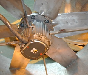
The way a motor is physically mounted in an application can make a huge difference to its performance, and the efficiency of the wider application.
There are four common ways of mounting motors:
There are international standards for foot mounted motors (Code B3/IM1001), C flange mounted motors (Code B14/IM3601) and D Flange mounted motors (Code B5/IM3001). This means that a motor of a particular frame size will be physically interchangeable with motors of the same size from other manufacturers. There are no such standards covering pad mounted motors so these can vary widely in design between suppliers, and usually require a unique mounting arm design.
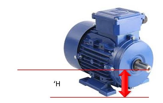
There is also a standard way of expressing motor frame sizes, which expresses the distance in mm between the centre of the shaft and the base of the motor foot (‘H’ in Figure Two), followed by a letter ‘S’, ‘M’ or ‘L’ denoting the length of the wound Stator (i.e. a short, medium or long core inside the motor). So a frame size of 160M would mean the motor was 160mm from shaft to base of the motor foot, with a medium core.
Overheating can be a problem in motors, and if it is not checked, physical damage can occur – so it is important that thermal protection devices are used to stop this happening. There are two main types of thermal protection device: The Thermostat Overheat Protector and the Thermistor.
A Thermostat Overheat Protector is embedded in the windings of the motor, and works on the same principle as the switch on a domestic electric kettle. It is designed to switch off the motor in the event of overheating. It has within it a small plate of two different metals bonded together.
As they heat up, the two metals expand at different rates, causing the disc to ‘dish’ This lifts the disc away from the two electrical contacts mounted either side, breaking the circuit. The temperature at which this happens can vary, but for standard electric motors it is 155°C, which is safely within the maximum operating limitations of the insulation system used in the motor windings.
These contacts will usually be connected in series with the contactor coil circuit of the motor starter, so that when they open, the contactor will drop out, allowing closer examination as to why the motor overheated.
A Thermistor is a small bead of semi-conductor material, the resistance of which varies with temperature change. The most common type is a ‘Positive Temperature Co-efficient’ (PTC). Which simply means that the resistance rises as the temperature increases.
They are supplied in sets of three connected together in series, which gives a set resistance reading when used in either a single phase or 3-Phase motor. These are buried in the end windings of the motor during its manufacture.
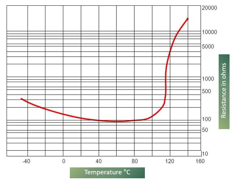
Figure Three shows the typical resistance characteristic of a Thermistor. Resistance is very stable across a wide range of temperatures, but once it reaches a certain point (120°C in this example), the resistance increases dramatically – from 100 ohms to over 10,000 ohms over just a few degrees difference in temperature.
Generally the Thermistor is regarded as the more reliable of the two types of thermal protection devices. Both can be retro-fitted to motors, but this is best left to manufacturers or rewind companies.
You might also be interested in:
Motor Basics - Part 1 which looks at the electrical principle that come into play during simple motor operations
Motor Basics - Part 2 which explores AC Motors and how they work
Motor Basics - Part 3 which looks at permanent magnet motor function
Motor Basics - Part 5 to understand better how to mitigate the issues that arise in some conditions
To find out more or to discuss your next project, please get in touch.