The types of motor most commonly used in Woods Air Movements fans are AC induction motors. These can run directly from the electricity supply, they are robust, they require little maintenance, and they are relatively low cost.
In a 3-Phase AC induction motor, coils of insulated wire are in the Stator slots located in the housing. These coils are configured to provide a set of electromagnetic poles for each of the three electrical phases (U, V and W) when powered.
Figure 1 shows a motor where the coils are arranged to provide a pair of poles for each phase (labelled U1 and U2, V1 and V2, W1 and W2). Because there are two poles for each phase, this is described as a 2 pole configuration; if there were two pairs of pole for each phase, this would be a 4 pole configuration – and so on.
When the coils in the Stator are connected to an AC supply, an electrical current will flow and produce a magnetic field – the coils are wound so that the poles in each pair have opposite polarities.
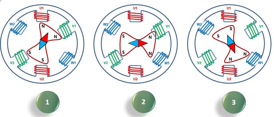
The cyclical nature of the AC waveform results in the magnetic field rotating around the central axis of the Stator, with two north and two south poles at any one time. The speed of that rotation is determined by the number of pairs of poles and the electrical supply frequency (either 50Hz or 60 Hz – see ‘Motors Basic Part One').
Where there is one pair of poles the magnetic field rotates once per electrical cycle; where there are two pairs, the magnetic field rotates once per two cycles, and where there are three pairs, it rotates once per three cycles.
The basic equation to establish the Synchronous Speed is as follows:
Synchronous Speed (rev/min) = 2 x Supply Frequency (Hz) x 60
Number of poles for each phase
So if the motor in Figure 1 was operating on a 50Hz supply, the synchronous speed would be:
2 x 50 x 60 = 3000 rev/min
2
It can be seen, therefore, that the higher the number of poles, the slower the synchronous speed will be – so a motor with 12 poles per phase would have a synchronous speed of just 500 rev/min.
Alongside the Stator, the most important part of an AC induction motor is the Rotor. This consists of Rotor bars, usually made of aluminium or copper, which are joined at their ends to rings made from the same material. This is sometimes known as a ‘Squirrel Cage’ Rotor (see Figure 2).
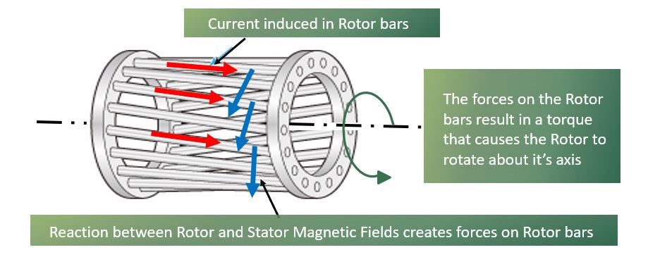
Because the Rotor is located in the rotating magnetic field of the Stator, the lines of magnetic flux that are produced will cut the Rotor bars and induce a voltage in the Rotor. This will in turn result in an electrical current flowing in the Rotor bars (indicated in Figure 2 by the red arrows), which will generate its own magnetic field around the Rotor bars. This magnetic field interacts with the Stator magnetic field to produce a force on the Rotor bars, causing the Rotor to rotate around its axis.
Because the voltage in the Rotor bars is generated by the magnetic field in the Stator cutting through the Rotor bars, if the Rotor rotates at a synchronous speed, there will be no relative movement between the Rotor bars and the Stator magnetic field – resulting in no voltage being induced in the Rotor bars.
If a load is applied to the Rotor, it will start to slow down, and hence it will begin to interact with the Stator magnetic field and torque will be produced as shown in Figure 2. It will be that torque which drives the load applied to the Rotor.
Synchronous speed is a function of electrical supply frequency and the Stator winding configuration (number of poles). The difference between the synchronous speed and the Rotor speed is known as Slip; this is expressed as a percentage of synchronous speed and can be calculated using the equation:
Slip = Synchronous Speed – Rotor Speed
Synchronous Speed
Figure 3 shows the construction of a typical Rotor. The Rotors bars are normally contained within slots in a steel core to enhance the Rotor’s magnetic field. The Rotor bars are usually skewed so that they are not in line with the Stator windings, reducing electromagnetic noise and providing a smoother transmission of torque.
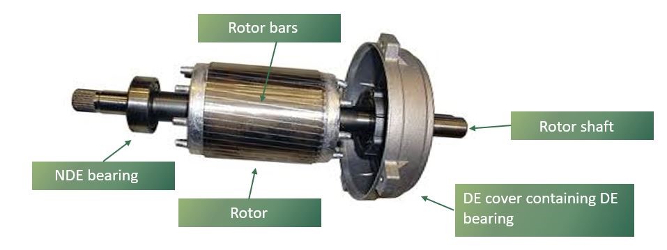
The core is constructed from steel laminations stacked together, whilst the Rotor bars and end rings are usually created by pouring molten aluminium into a die or mould that surrounds the Rotor lamination pack. This molten aluminium flows through the slots in the Rotor pack to form Rotor bars. There is no insulation between the Rotor bars and the steel core, because the induced voltage is low.

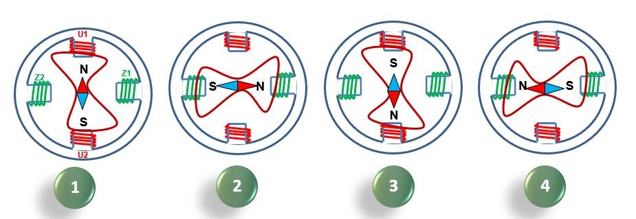
A Stator configured for a single phase supply will not be able to initiate the rotation of a Stationary Rotor, because its magnetic field will simply flip between polarities. As a result, an additional winding is required to provide a progressively rotating magnetic field. This auxiliary winding is connected to the single phase supply via a capacitor, so that its voltage waveform can be out of phase with that of the primary winding.
Figure 5 shows how this creates a continuously rotating magnetic field, allowing for rotation to be induced.
You might also be interested in:
Motor Basics - Part 1 which looks at the electrical principle that come into play during simple motor operations
Motor Basics - Part 3 which looks at permanent magnet motor function
Motor Basics - Part 4 to understand the physical considerations when selecting a motor
Motor Basics - Part 5 to understand better how to mitigate the issues that arise in some conditions
To find out more or to discuss your next project, please get in touch.